You can also use the following checklist to simplify any commissioning
All operations and inspections are to be carried out as per the installation instructions before commissioning. The following tasks are then to be executed:
Make sure there is correctly scaled ventilation and aeration in the installation area. (Take into consideration increased power loss with the AF-operation). For your own dimensioning, guidelines from the worksheet J11 transformer stations can be used and sent on request.
For dismantled parts for transport such as connection lugs, remove and assemble control boxes etc. from the packaging.
The chassis supports must not be disassembled from the lower clamping bar!
If protective enclosures are supplied, assemble them in accordance with the schemes enclosed.
If there is a big time gap between installation and commissioning and there is a risk of contamination e.g. from dust by the construction site, then please follow the directions in Cleaning the transformer.
Check that the upper support blocks sit firmly. The rubber bases must then be compressed a little. If necessary, retighten the pressure screws. As a guideline it is important that the rubber is thereby pressed 2 to 3 mm into the coil. For a more accurate value please consult SGB
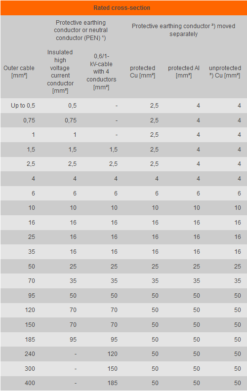
Connect and check the earthing and potential equalisation on the transformer correctly. In a standard case the connections are on the chassis. Please bear in mind here the torque of the fixing screws and the minimum cross-sections of the potential equalisation conductors. The cross-section of the potential equalisation conductor must be at least half as big as the largest protective earthing conductor cross-section of the installation, but at least 6 mm² of copper for mechanical reasons. For potential equalisation conductors, 25mm² copper is mentioned for non-electrical installations as a satisfactory upper limt. Other than that the whole protective earthing conductor of 50 mm² is to be chosen as a cross-section for the potential equalisation conductor.
Assignment of the minimum cross-sections of protective earthing conductors and neutral conductors to the cross-section of the outer cable in accordance with the Association for Electrical, Electronic & Information Technologies 0100, part 540:
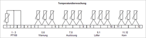
Connect temperature monitoring systems and check for functioning by means of an interruption of the sensor circuit on the marshalling panel.
If fans are available, check the correct direction of rotation of the fans and the functioning of the control system (see circuit diagram temperature monitoring).
Carry out phase connections in accordance with circuit plate. In doing so, be mindful also of the correct position of the converter bridges.
Check and retighten all screwed electrical connections.
Torques CU rail connections:
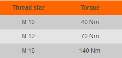
Torques high voltage circuit lugs und sprue bushes:
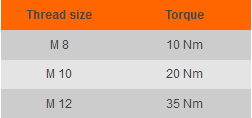
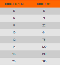
Torques for fixing screws with cable lugs. Following the German Institute for Standardisation and the Association of Electrical, Electronic & Information Technologies 0220 part 2 the following torques are to be adhered to for screws of strength category 8.8:
Check all connection cables for strain relief. No mechanical strain to be conducted on the transformer connections.
Check voltage intervals:
Keep all lead wires and control wires, as well as attachments and auxiliary parts at a satisfactory interval to the high voltage cast resin coil. We recommend you keep to intervals as with bare, live conductors in accordance with the Association of Electrical, Electronic & Information Technologies 0532:
Attention! The high voltage cast resin coils are indeed insulated with a cast resin layer, however they are not scoop-proof in the terms of the regulations of the Association of Electrical, Electronic & Information Technologies, i.e. when working with the transformer or in the immediate vicinity of which it is only permitted in a dead and earthed state.
Insulation measurements
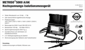
With 2,5 kV DC the insulation resistances are measured with the high voltage insulation meter Metriso 5000 (see picture).
The following measurements are to be carried out:
The values measured are to be compared with data on the check sheet. (Guideline: 1 MOhm per 1 kV, e.g.: 0,4 MOhm with 400V)
Important: Before measuring PTC, remove high voltage and low voltage connection cables!
Attention: in humid weather conditions the insulation resistance falls!
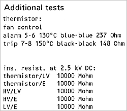
Measure PTC ohmic resistances and PT100 and compare with values on the check sheet:
PT100 are measured twice (always to the combined white conductor): here from terminal 1 to 2 and from terminal 1 to 3. The PT100 resistance is 20°C ambient temperature ca. 110 Ohms.
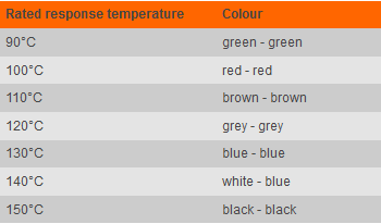
With PTCs not every single resistance is measured but the entire series connection of the PTCs: here between terminal 5 and 6 and 7 and 8, and 9 and 10, and 11 and 12. The total resistance of the 3 switched thermistors in a row (PTCs) is 20°C ambient temperature between 60 and 750 Ohms.
Attention: when checking the cold conductor resistance of the thermistors, the voltage to be measured from the meter should not be above 2.5V!
Example: Data on check sheet
Summary of the PTC's used by SGB
Hints on transport or storage:
During transport of the cast resin transformer to the site, weather conditions, for example, high humidity, can bring about lower values for insulation resistance, lower than those indicated on the SGB check sheets. The transformer can nevertheless be switched on safely. If in doubt please get in touch with SGB