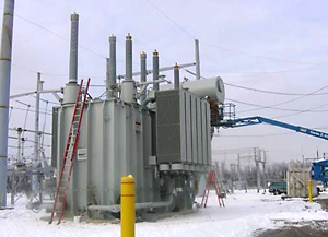
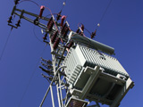
At higher voltages, large auto-transformers are used to interconnect the 400kV-500kV systems with either the 230kV-275kV systems or 120kV-145kV systems (the exact values depend on the country being considered).
The HV and MV windings in an auto-transformer are connected together unlike in other transformers. The result is that the MV winding (common winding) is shared between the MV and HV systems. This results in a smaller and less expensive transformer than if the windings were separated as in a conventional fully rated two winding transformer.
However, this is only advantageous if relatively close voltage ratios are used. A separate delta connected tertiary winding may be provided for harmonic suppression or for the supply of local loads at lower voltages.
These auto-transformers are generally more complex than generator step-up transformers and their dielectric design more difficult. Their performance under short-circuit has also to be carefully analysed at the design stage, as they are connected to large systems with high short circuit fault capacities capable of the bulk infeed of fault current during a short circuit on the external system.
Royal SMIT Transformers B.V. has an ongoing engineering evaluation process for continuous improvement and upgrade of its design programs.
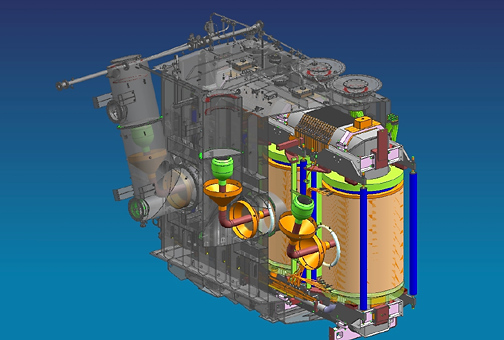
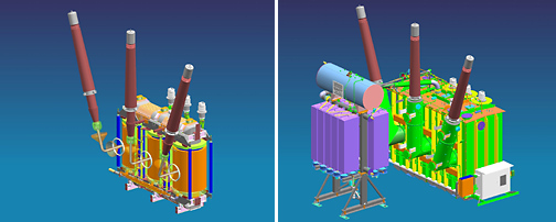
Royal SMIT engineering is making full use of a high end 3D-CAD system for the complete transformer design. Active parts and tanks can be combined in one model allowing the best possible check on correct dimensioning.
Almost all engineers use 3D-CAD stations. The introduction of 3D-CAD technology was thoroughly prepared over the past years. A team of experts worked fulltime on the required tank- and active part models.
The great advantages for SMIT as well as its customers are:
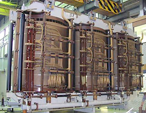
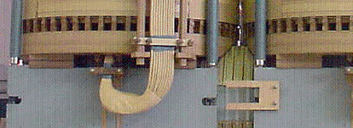
Royal SMIT Transformers B.V. produces large power transformers with independent clamping of the core and windings. This clamping system is unique amongst manufacturers of large power transformers.
The independent clamping arrangement has many advantages:
Royal SMIT style windings differ from most of our competitors in having axial cooling ducts without pressboard radial spacers. This type of winding style has several advantages:
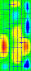
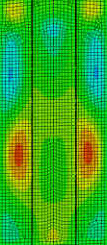
Royal SMIT Transformers B.V. has developed finite element models of the transformer tank design allowing the tank stresses and vibration levels to be accurately predicted:
Reliable Transformers with the unique single winding clamping construction are shipped wordwide to customers producing power. We have extensive experience with requirements for the nuclear industry and the renewable energy. The single winding clamping construction gives additional strength regarding short circuits and does not influence the core clamping.


Large Power Transformers have been delivered for customers choosing for Transformers with a long life span, high reliability and with the approved unique single winding clamping construction.

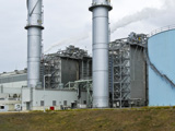
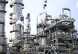
Reliable energy supply in all production processes is of main importance for our customers. Reliable Transformers are part of this philosophy. Our Transformers have been delivered all over the world for multiple industries chosing for quality and reliability.

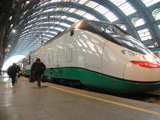
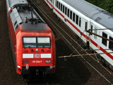
Short Circuit Resistance is a major concern for customers within the railway industry. That is why our Transformers are chosen, being very reliable due to the unique single winding clamping construction and the high quality of our Transformers.